The complex loads associated with today’s commercial and industrial sites require careful consideration to achieve safe and reliable earth-leakage protection for the installation. UPS, HVAC, Battery chargers and other inverter based products may not be suitable for use with standard residual current protection devices (RCDs), due to the specific types of earth leakage current that can be produced by these 3 phase loads.
Competent Person
General guidance on the process and checks to select residual current protection can be found in the current Regulations. However guidance on the “Type” (see below) of protection required for an inverter based product should be clearly stated in the equipment manufactures installation instructions. The topology of the inverter product (semi-conductor schematic and possible use of isolating transformers) will determine the type of RCD required.
In addition to the normal everyday electrical knowledge, an understanding of the earth leakage characteristics of the load, the impact on the protective conductor specification and the operation of the (RCD) makes the process relatively simple.
The Regulations make specific reference to the use of national and international standards where the information is not contained within the Regulations. EN50178 gave some representational schematics of power electronics and the associated leakage and fault currents – see Doepke Application Guide page 30
Any gaps in knowledge, supporting information and the selection process, can result in an unsafe and unreliable installation, with the potential to cause serious injury or death from electrocution and or fire. In cases of Criminal Negligence – “Ignorance of those things which a person is deemed to know is no excuse”
Earth leakage current
As we are aware, all healthy circuits generate leakage currents. Issues arise when the characteristics of the leakage current are ignored and consequently interfere with the safety aspects of the installation.
Residual current is defined as the algebraic sum of the earth leakage currents measured at a given point in an installation. This quantifies the value but not the specific components/characteristics of the leakage currents that make up the residual current, or the effect on associated products and circuits: see – Reg. 331
Inverter installation manuals often quote the residual current at 50Hz for example 3.5mA, however the leakage currents at the inverter switching frequency and EMC filter frequency will be significantly higher and cannot be ignored. If the information is not given in the manual, contact the manufacturer for advice and a written response for your own records.
The Regulations lay down specific requirements for residual currents above 3.5 mA, and anything above 10mA i.e. let go threshold, will require additional steps to be taken with regard to the selection, installation and connection of the protective conductor – Reg. 543.7
Accidents and serious injuries can occur at quite low levels of current and high frequency leakage currents might not cause an immediate heart attack, but they do fry meat very nicely on the surface. For a normal dry and clean environment, the use of the correct “Type” of 30mA RCD will substantially reduce the risk of a fatality. However it may not be compatible with the average inverter installation – discussed later in the article.
For fire protection the limit is set at 300mA providing the installation/location is considered to be a low fire hazard – Reg. 422.3.9 / 532. Much lower levels of leakage current can cause carbonisation and ignition of deposits on insulated surfaces, leading to the possibility of a high resistance earth fault (worst case).
Type of residual current
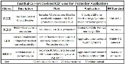
AC loads depending on their nature can produce leakage currents at mains frequency, at high frequency, pulsed DC and smooth DC. The type of leakage currents present in a given installation will determine the “Type” of RCD that can be used safely, within the system for People or Fire protection. The standards define several basic types of residual current, see summary below:
|
Residual Current |
Characteristics |
Example Loads |
|
Type AC |
|
Resistive heating /lighting |
|
Type A |
|
Single phase switch mode power supplies |
|
Type B |
|
3 phase VSD AC/DC converters |
|
Type F |
|
Single phase power hand tools |
|
Note 1: Refer to the RCD manufacturer’s characteristics for frequency limits |
||
Select the RCD based on the load
The correct selection process for residual current protection takes into account the leakage currents present under normal operation and leakage currents under fault conditions. Any transients or phase imbalance created by the load during switch-on, running and switch-off could create unwanted tripping of the RCD if the level of protection or type of protection selected is not appropriate for the load: – see Reg. 331
In figure 1 connecting the machine to the same circuits used by service staff would contravene Reg. 314.2

Where necessary, loads must be segregated to achieve the required protection levels for staff and the installation plus discrimination for supply continuity: – see Reg. 314
If the RCD cannot detect the leakage current e.g. outside of the designed frequency range, or the magnetic circuit is saturated (dc superimposed on the ac wave form) it will not trip. Obviously protection will only be maintained if the RCD is working within its original design limits.
Residual current devices
The devices listed in the table below can be used in residual current protection applications and are based on the defined EN Product standards.
Generally for applications under 125A involving non-skilled staff, the preferred formats are RCCB and RCBO with non-adjustable settings.
CBR and MRCD’s incorporating adjustable current/time characteristics will have a method for sealing the setting, to prevent unauthorised adjustment following commissioning, testing and completion of the Electrical Installation Certificate, including the recording of the set values.
MRCD + MCCB used for 30mA protection must be based on tested combinations to prove the disconnection times.
RCBO’s generally are restricted in the range of applications that they can be used for, however RCCB, CBR and MRCD’s offer a wide range of formats: Type A and Type B with time adjustment ranges suited to the higher protection levels and current requirements of complex commercial and industrial installations.
With critical process applications and commercial sites, it is possible to build in pre-alarm conditions/insulation monitoring to ensure that early warning is given of potential earth faults developing in particular areas or circuits, enabling immediate remedial action before the RCD operates and disconnects the supply.
Doepke offer a comprehensive range of RCD and RCM units for Type A and Type B residual currents, with full technical back up and customer support based in the UK. sales@doepke.co.uk
Chaz Andrews – Technical Manager, Doepke UK Ltd
If you would like more detailed information relating to this subject, Doepke UK have a free 60 page Technical Application Guide: log on to www.doepke.co.uk to download the guide or obtain further information on RCDs.